You are the

th visitor since 4 July 2000

: Contents viewable in the Japanese font ONLY.
The personal information provided by this form is appropriately preserved by the relevant laws and the NIFS/NINS regulations. With the consent of the corresponding primary investigator (representative researcher) in case of NIFS/NINS collaborators of other organizations, it will be used for communications concerning the LHD information system operations, and the management and statistical processing of collaborative uses. The personal information provided will not be used for any other purposes than above mentioned.
In order to apply or reply to the online form of this web site, it is necessary to agree to the above mentioned rules. If you consent, please press "Submit" to proceed, or otherwise leave the page to cancel.
Please be sure to read the above policy before entering and sending personal information from any forms.
Install a diagnostics system
Follow the steps below to set a new diagnostics data-collecting system.
-
Configure digitizer and decide where to install
Decide what modules and how many units of them to use (including the
number of channels to use, sampling speed, digitizer category, etc…).
Decide where to install.
*The LHD main room and the LHD basement room of the LHD building are better to be excluded considering future work of the device's upgrading.
-
Check module availability
Check the list of available modules . If the modules you wish to use are
on the list, apply for the joint purchase of modules. If not, make a
request for the use of modules yet to be listed.
. If the modules you wish to use are
on the list, apply for the joint purchase of modules. If not, make a
request for the use of modules yet to be listed.
*Please understand that it may take time to prepare a new module.
-
Apply for installation
Name the diagnostics system. Name the modules and give them station/device numbers. Apply for
the installation/argumentation of a diagnostics system.
-
Purchase required peripherals
Buy what is necessary among the options below at our online shop, LABCOM/X Original Products e-Shop.
-
Prepare for data transmission
Follow the directions given to the place to install. (Details will be given to you on a case-by-case basis.)
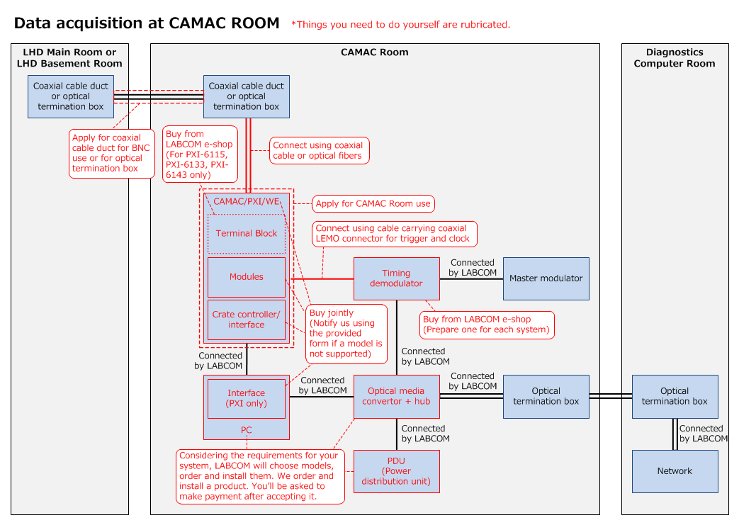
 The
Data Acquisition Room in the first basement of the LHD Building (the CAMAC Room)
The
Data Acquisition Room in the first basement of the LHD Building (the CAMAC Room)
-
Channel planning
Check the layout of coaxial cable ducts and optical termination boxes and decide how to set up a channel for your system.
-
Apply for CAMAC Room use
Make request for CAMAC rack power use/wiring/carrying in devices into the CAMAC Room.
-
Prepare for data transmission
Have everything ready for data transmission, such as setting crates/chassis/stations, inserting modules, installing a crate controller/interface and connecting cables.
*Hand the interface to PCs to LABCOM (This is for PXI only).
*LABCOM will make preparation for data-collecting system (i.e. PC) and network connection.
-
Install diagnostics timing demodulator
Place a timing demodulator and have it connected to the CAMAC/PXI/WE using a cable carrying a coax LEMO connecter for trigger and clock.
LABCOM will take care of the wiring of the timing demodulator to the master modulator as well as the network connection of the device.
-
Contact LABCOM
Call 2452 or send an email to  when things are all set.
*LABCOM will test the system and let you know whether it is working properly.
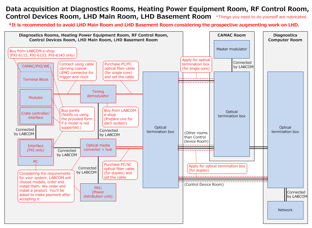
Diagnostics Rooms, Heating
Power Equipment Room, RF Control Room, Control Devices Room, LHD Main Room, LHD Basement Room
*The LHD Main Room and the LHD Basement Room are better to be excluded considering the prospective LHD augment work.
- Channel planning
See the layout of coaxial cable ducts and optical termination boxes and decide how to set up a channel for your system.
-
Prepare for data transmission
Have the system units ready for data transmission, such as setting crates/chassis/stations, inserting modules, installing a crate controller/interface, connecting cables and so on.
*Hand the interface to PCs to LABCOM (PXI only).
*LABCOM will make preparation for data-collecting system (i.e. PC) and network connection.
-
Secure network channels
Secure duplex channels between an optical media convertor and the Diagnostics
Computer Room of the LHD Control Building, which is necessary for network connection.
-
Purchase an optical fiber cable as follows:
FC/SC duplex cable 1pc:
This is for the connection within a same room between the convertor to an optical termination box.
-
Check the list of optical termination boxes in use to see whether a duplex channel from the installation location to the CAMAC Room/the
Diagnostics Computer Room is available or not. Make
request for the use of optical termination box to secure the channel.
*LABCOM will set up a channel beyond the CAMAC Room.
-
Connect the converter to the allotted termination box via the optical fiber cable that you have purchased.
*Please lay an optical fiber cable beneath a raised floor or using a cable-through ladder.
-
Install timing demodulator
Bring in a diagnostics timing demodulator and have it connected to CAMAC/PXI/WE using a cable carrying a coax LEMO connector for trigger and clock.
*LABCOM will handle the network connection of the demodulator. Let us know where you install the device. Call 2452, or send email to
.
-
Secure channel to master modulator
Secure a single-conductor channel for connecting your demodulator to the master modulator at the CAMAC Room.
-
Purchase an optical fiber cable as follows:
FC/FC (single core) cable: 1 pc
This is to connect between the demodulator and an optical termination box in the same room.
-
See the list of optical termination boxes in use to check if there is a single-conductor channel available from the room to the CAMAC Room. Make
request for the use of an optical termination box for the connection.
*LABCOM will take care of the wiring within the CAMAC Room from the termination box to the master modulator.
-
Have the timing demodulator connected to the allotted optical termination box via the optical fiber cable that you have purchased.
*Please lay optical fiber cables beneath a raised floor or using a cable-through ladder.
-
Contact LABCOM
Call 2452 or send email to when things in the room are all set.
*LABCOM will test the system and let you know whether it is working properly.
-
Set digitizer and timing
Go to the Setting for Data Acquisition to set the digitizer's operation parameters. Click here to see how to do the setting. To configure timing (trigger and clock), you need to download and install a software application “Plasma Diagnostics Control Client System”, through which you set timing parameters. Click
here to see how to install/use the software.
-
Test performance
Before starting your system, you may have calibration data using the LABCOM system. Go to Test with LABCOM System.
-
See collected raw data
Download and install Retrieve, a program of diagnostics data acquisition procedure, so that you may have a look at raw data/one-stage processed data. Click here to see how to use Retrieve.
Now, you are all set for the diagnostics.