Instructions for Installing Timing Demodulator Box
Created by NIFS-LABCOM in Sep., 2008
(Revised on Dec. 10, 2008)
1. About the product
Timing Demodulator BOX (referred hereinafter “Demodulator BOX”) is LABCOM's original product, upgraded from the VME version (8736) by increasing the number of clock channels from two to six while maintaining compatibility with the previous version and reducing a price to the one-eighth of the VME model.
2. Steps to install
Operating the Demodulator BOX needs optical fiber link and network cable connection.
Optical fiber connection
Have the Demodulator BOX connected via optical fiber cable so that it receives optical signals of diagnostics timing (trigger and clock). Please note that the link peripherals used to the VME version are now out of production, and therefore the Demodulator BOX employs different models.
[If you wish to replace the VME version with the Demodulator BOX]
You don't have to prepare another optical cable for the upgraded demodulator. The access destination recognized by an optical divider in the CAMAC room has to be renewed. LABCOM will take care of this renewal, so let us know the port number of the optical termination box that you use.
[If you wish to newly set the Demodulator Box]
Cabling is necessary between the Demodulator BOX and an optical divider in the CAMAC room. In doing so, apply for the use of an optical termination box through an online form (There's one port to be necessary).
For applying to use an optical termination box: http://w3.lhd.nifs.ac.jp/en/Service/Request/form/OpticalTermination_rq-e.php
Lay an optical-fiber cable between the Demodulator Box and the termination box by yourself while LABCOM will take care of the cabling between the termination box and a divider in the CAMAC room.
Network cable connection
You configure the Demodulator BOX via the subnet (133.75.175) called the Diagnostics and Control Network. Therefore, the device basically has to be connected to the network, but optionally able to be linked to another sub-network in certain places. Besides, this process should be done according with the instructions given by the Experiment LAN team. Contact us when you decide where to set.
3. Install “Plasma Diagnostics Control Client System”
The configuration of the Demodulator Box parameters is made using “Plasma Diagnostics Control Client System”, a software application for Windows PC. Download and install the software through the URL shown below (See Ref. 1.).
For download:
http://w3.LHD.nifs.ac.jp/en/LABCOM_Download-e.htm#control
The VME demodulator could be also configured through the application, and you don't have to keep the older version.
The Demodulator Box has its own IP address and a default account. The username and password will be given to you along with a product when it is delivered, which is necessary to log in before using the device. The account information is editable. Go to the following URL and make a request for the change of the information.
For changing to change account information:
http://w3.lhd.nifs.ac.jp/en/Service/Request/form/DemodulatorPassword_rq-e.php
The Demodulator BOX has a similar interface to the one of the VME, but its function has been improved and now you may set trigger and clock parameters for six channels individually on a same window. Ref. II will tell you more about how to use the software.
[Ref. I] For Installing “Plasma Diagnostics Control Client System”
(NOTE) If you already have this program and you wish to install one to a different location in your computer, make sure to delete two files named “DataServer.INI” and “plasma.INI” before starting installer. These files are located in the System Folder and the User Profile Folder (the folders identified by the environment variables of SystemRoot and USERPROFILE). This process is unnecessary if this is the first install, or re-install over the existing version.
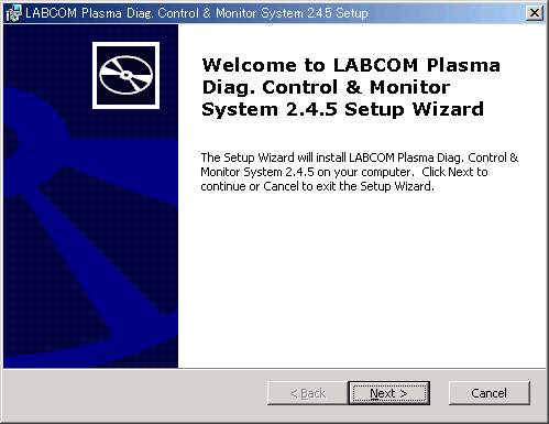
Click Next> to proceed.
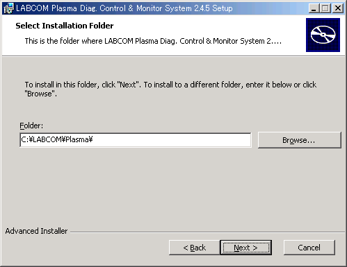
Specify a destination folder where the program should be installed or accept the default.
Confirm the installation.
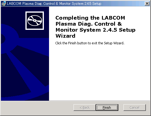
Press Finish to complete the installation.
[Ref II] How to use “Plasma Diagnostics Control Client System”
Click on Start>Program>LABCOM Plasma Diag.Contrl. System>Connecting VME IP address. The initial settings of the “PLASMA計測制御SYSTEM 環境ファイル”, or PLASMA Diag/Contrl SYSTEM's Configuration File, is as shown below. The last part of the file needs to be changed for your use: replace “Diagnostics
Computer Room” with the installation site and “133.75.175.180” with the IP address given to your Demodulator Box.
If nothing is shown when the file opens, try to run the program via Start>Program> LABCOM Plasma Diag.Ctrl. System> Plasma Diag Ctrl. System.
#
# Environment file for PLASMA DIAGNOSTICS AND CONTROL SYSTEM
#
# '#' indicates that is a comment line.
# '$' separates chassis, and the IP address of a destination VME (a communication CPU) follows that symbol.
#
#####
# DTS Primary/Secondary Modulation ... CAMAC Room ... VME26
#$ 133.75.175.200
#
# Heating Secondary (Relay) Modulation ... Heating Device Room NBI
#$ 133.75.175.192
#
# CAMAC Room Demodulator CAMAC Rack#01 ... VME01
#$ 133.75.175.100
# CAMAC Room Demodulator CAMAC VME Rack#25 ... VME25
#$ 133.75.175.196
# CAMAC Room Demodulator CAMAC Rack#19 ... VME31
#$ 133.75.175.220
# CAMAC Room Demodulator CAMAC Rack#20 ... VME32
#$ 133.75.175.224
#
#####
# Diagnostics Computer Room ⇒ (Change to where you set the device)
$ 133.75.175.180 ⇒ (Change to the IP address of your Demodulator BOX)
#####
After saving the configuration file, start the program via Start>Program> LABCOM Plasma Diag.Ctrl. System> Plasma Diag Ctrl. System.
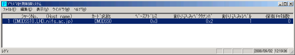
If there isn't any problem, you will see a window box shown above. Under the
“シャーシNO. (Host name)”, the host name of your Demodulator Box will be shown in a way like
“1 (DMODSS**.LHD.nifs.ac.jp)”. The part of ** should be identical to the one of
“TDF10**” shown on the product label. Then, click “編集(Edit)”> “I/Fカード設定/変更(IF Card/Configure/Modify)” and log in with the username and password that you have.
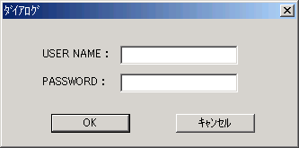
When you successfully log in, a configuration box as shown below will appear. If you give a wrong password, the box will open but be for read only.
[NOTE] Please make sure to close the box by clicking one of the buttons in the bottom, either OK or キャンセル(cancel). You could exit the program using the close box, but the program wouldn't recognize the connection has quitted. Next time you access the program, it would open in a read-only mode even though you log in correctly.
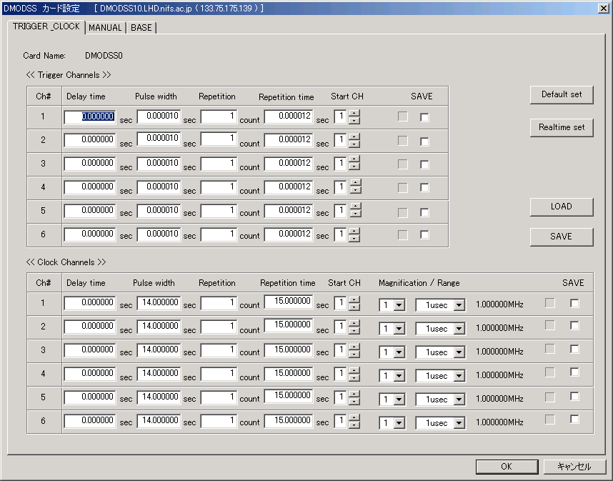
Set parameters for trigger (the upper half of the dialogue box) and for clock (the bottom half). You normally don't have to change any values on the “Manual” and “BASE” tabs.
[FYI] We are happy to tell you that trigger and clock are now able to be configured independently channel by channel with the Demodulator BOX, which weren't possible with the previous VME version.